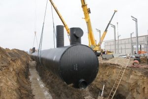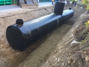
Sedimentation plants are structures for the mechanical treatment of rainwater or wastewater.
The systems are designed as standard for traffic loads of up to SLW 60 (10 t wheel load) and groundwater levels up to the top of the tank. However, higher traffic loads and groundwater levels are possible upon request. The structural analysis is carried out depending on all forces resulting from traffic loads, groundwater pressure and installation depth.
 The system is characterized by high stability and resistance. Due to their low weight, they are easy and quick to install even in the tightest spaces. A comprehensive quality assurance program ensures excellent quality of each tank.
A buoyancy check and a static calculation are supplied on request. A sophisticated process is used to prevent the tank from floating up in the event of rising groundwater, if necessary.
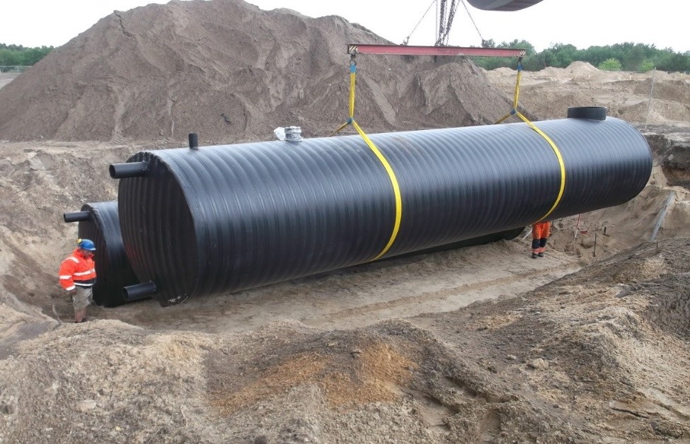
Despite the enormous stability, SABUG sedimentation plants have a low dead weight, which enables a quick installation of the prefabricated elements. No truck-mounted crane or other heavy equipment is needed.
Advantages
- High static stability – up to traffic loads SLW 60
- High stability against groundwater
- High chemical resistance
- Low weight due to lightweight construction
- Double wall construction
- Flexible adjustment of the required volumes
Function of the equipment
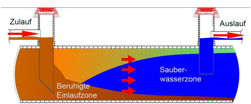
The basis for the functioning of these plants is the separation of non-dissolved components of water of different density by using gravity. The engineering design follows the specific rising and settling behavior of the individual materials. Thus, using the so-called Stokes equation, a time can be determined that is required to allow the corresponding components of the wastewater contamination to float or settle. In addition to the density, the size of the respective particle is also decisive.
The use of Stork’s equation basically assumes an undisturbed settling space. For this reason, the calculation is corrected by the actually determined slump values (according to DIN 18123 “Subsoil, examination of soil samples – determination of grain size distribution”).
Sediment and floatables will be stored in designated areas of the facility and disposed of according to the maintenance schedule. The design of the plant must ensure that remobilization – i.e. “re-suspension” of the substances once they have settled – is not possible.
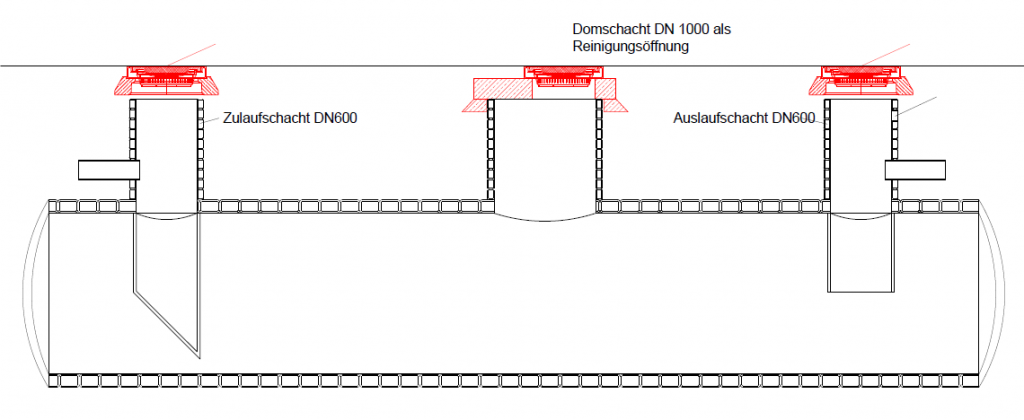
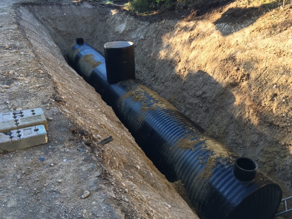
The SABUG sedimentation units have a sedimentation pipe of at least 1000 mm and an access opening of min. 600 mm. This allows the entire plant to be walked on if required. Cleaning is usually done by suction. In the event of an accident, the system is equipped with an oil barrier that reliably prevents the discharge of light fluids.
To simplify planning, the DWA – German Association for Water, Wastewater and Waste has developed corresponding worksheets, which are used today in the calculation of cleaning performance. DWA-M 153, DWA-A 138, DWA-A 116 und DWA-A 117.
SABUG sedimentation plants are also designed according to these specifications.
For the design, specified boundary conditions and specifications regarding the hydraulic requirements of the guidelines are used. First and foremost, of course, the volume flow rate with which the system is fed plays a decisive role. This is the product of the connected area and the relevant rainfall donation. Taking into account the passage values required according to DWA-M 153, the max. flow velocities in the sedimentation pipe and the permitted surface feed, the dimension of the plant is calculated by us.
The necessary length of the cleaning section for the sinking of rock particles of 0.1 mm is determined. If necessary or desired, however, also the required settling length of diesel/gasoline fuels. The system can therefore also be designed for light liquid separation in accordance with DIN EN 858-1. Since the calculation system assumes a laminar flow ratio, the area approx. 1 m downstream of the inlet is taken as the cleaning section.
Calculation of the sink rates:
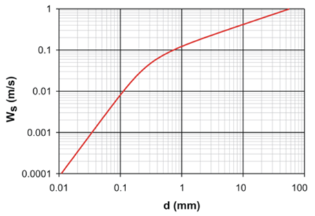

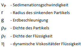
For the design of the plant, the expected contaminants are investigated with regard to their buoyancy as well as settling behavior. The following substances with the corresponding densities can be used as a basis for calculation. The corresponding sedimentation rates are obtained as follows:
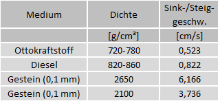
The sinking or buoyancy determination of the substances are determined through the entire pipe diameter as shown above and are distributed undefined depending on the nature of the water. The large diameter of the sedimentation pipe (min. DN 1000) enables effective cleaning. For larger installations, we recommend the arrangement of the additional access opening. This makes it much easier to dispose of sediments and floating materials.
Sedimentation plants within the meaning of DWA-M 153
The passage values of the sedimentation plants are determined according to Table A.4c. of the DWA-M 153.
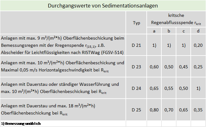
Classification of the plants in the DWA-M 153 leaflet
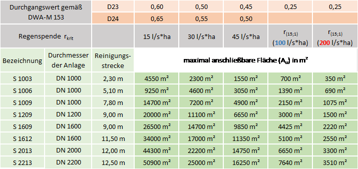
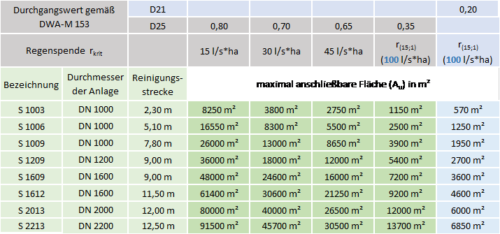
Hydraulic calculation
In order to ensure that the system is not hydraulically overloaded, it is important that the maximum calculated critical rainfall discharge cannot be exceeded. Otherwise, there is a risk of the settled sediments being stirred up and, in extreme cases, of the deposited particles being completely washed out. To ensure this, the system is designed by us in accordance with the guidelines and throttled at the inlets according to the critical rainfall runoff donation at the inlet. This prevents a too large volume flow from entering the system. The drainage of excess rainwater should be done through a bypass. This method is known in the literature as “overflow threshold” in concrete structures.
Quality assurance
High-quality professional planning and design is a fundamental condition for a successful project. SABUG GmbH has optimized this approach. Each tank receives detailed documentation with delivery to ensure that the drainage system meets the requirements of the inspectors.
Buoyancy safety
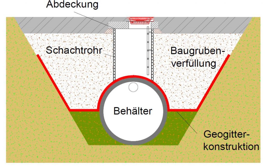
SABUG tank systems are inherently extremely lightweight with high stability. This offers an enormous advantage during transport and installation, poses the risk of the tank floating up in case of improper installation in the presence of groundwater. To prevent this, Sabug has developed a system that safely prevents floating. By using a special geogrid with very high tensile strengths, the container is held securely in place. SABUG’s expertise also lies in the technical design of the geogrid structure as well as the preparation of comprehensive installation instructions to ensure that the system works as intended.
This means that expensive concrete foundations, steel band constructions or the like can be dispensed with.


